CAD Drafting Basics
CAD Drafting Basics
Overview
CAD (Computer Aided Design) refers to software systems that are used in the drafting, creation, modification, analysis, or optimization of a design. As opposed to hand drafting, CAD drafting increases productivity improves design quality and design communications. CAD drafting is used for architecture, engineering and construction (AEC), as well as machining and manufacturing.
CAD drafting can be used in many different fields. In electronic design, CAD drafting is known as EDA (Electronic Design Automation). In mechanical design, it may be called CAD or CADD (computer-aided design and drafting. There is also CAE (Computer Aided Engineering) and CAM (Computer Aided Manufacturing). CAD is used in almost all branches of engineering, while CAM technology is more prominently used in Mechanical, Automobile, and Aeronautic engineering. Regardless, all of these forms have as their basis, fundamental CAD Drafting.
CAD drafting software may use either vector (line) based graphics to depict the objects of traditional drafting, or it may produce raster graphics or even 3D graphics which show the overall appearance of designed objects. Moreover, CAD drafting involves more than just shapes. As in the manual drafting of technical and engineering drawings, the output of CAD must convey information, such as materials, processes, dimensions, and tolerances, according to application-specific conventions. The difference between CAD drafting and hand drafting is that the materials, process, specs, etc. reside in a computer database and are related both rationally and spatially to the drawing.
There are many different software packages that can be used for CAD drafting, depending upon the type of CAD drafting (CAM, CAE, EDA, etc.) Some of the available CAD software packages include AutoCAD, CATIA, Solidworks, Microstation, and others. Regardless of the type of CAD or the software used, there are certain basic CAD Drafting procedures.
Basic CAD and CAM Drafting Procedure
CAD Design Phase
The process of designing, whether a consumer product, an airplane or a building is an interactive process which generally encompasses six steps:
Recognition of need – whether the need is a more powerful computer, a faster fighter jet, or a taller building – the first step is recognizing and defining the need.
Definition of a problem – as the need is defined, the problem that is incumbent on the need becomes apparent.
Synthesis – of the problem with the solution
Analysis and optimization – ensuring that the product solves the problem in the best fashion possible.
Evaluation – reviewing the product, the costs, and the processes involved in a production
Presentation – of the design.
Using 3D CAD Drafting as Part of the Process
Whether moving from a 2D design the 3D model to prove operability or drafting from the beginning in 3D, the purpose of a 3D Model is to “prove” according to the engineering concept, the customer requirement, and product design.
Further, the 3D model can be more fully analyzed than a 2D design by testing loads and checking the results in the analysis section of the software
After analysis, a final model is created within the software. This final model is often called the “masterpiece.”
CAD Drafting for CAM
If this is a CAM operation, then a die can be created in the mold section of the software where all the tools of die design are available.
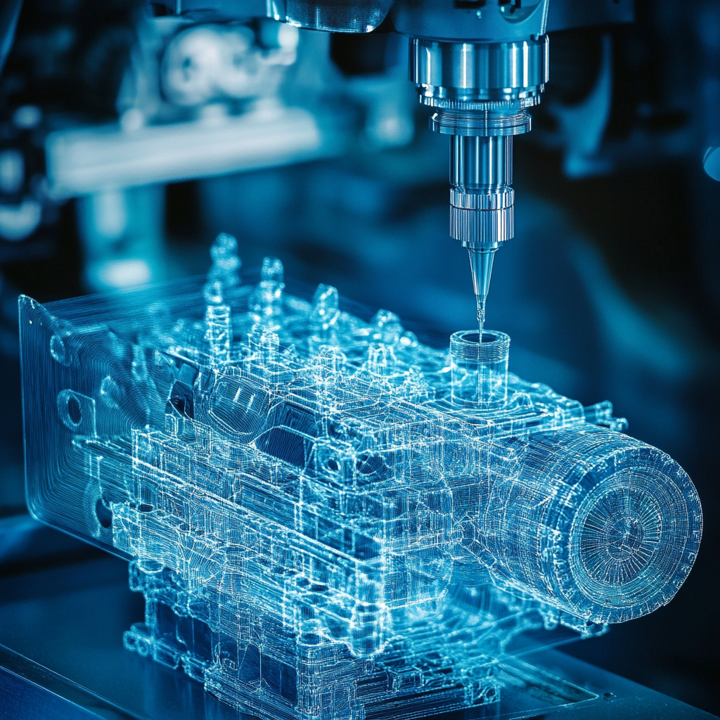
In this instance, then the model is sent to the Computer Aided Manufacturing (CAM) section of software where milling machines parameters like feed, speed, depth of cut, stock, stepover, cutter information, cutting pattern, coolant on/off etc. can be included.
Finally, the software can create a virtual model that can be visualized and checked for manufacturing accuracy. Once the manufacturing operation is verified, then a computer-generated list of instructions called the CNC program is sent to CNC machine, which performs the operations on a real piece of work. This real component is the exact replica of the model created in the CAD / CAM software on the computer.
CAD Drafting Conclusion
All types of CAD Drafting programs and CAD Drafting procedures are used in many different industries today. These software programs provide drafters and designers with the ability work quickly and accurately. This technology has revolutionized all types of design and drafting and increased competition among manufacturers in the global market. Hundreds of new models of all types of products can be produced due to the advances in CAD Drafting technology.
Recent Posts


5 Common CAD Mistakes and How to Avoid Them
We came up with 5 common issues that we see, and our expert advice when it comes to avoiding these issues.

Techniques to Save Money on Manufacturing Your 3D CAD Model
Our team of outsourced CAD experts wants to talk about ways that your engineering team can save money on manufacturing with each 3D CAD model in 2024.

Shortcuts to Save Time on CAD Conversions
a quick tip to save money on each of your CAD conversions
