Case Studies
CLIENT’S INTRODUCTION
Our client, a multinational firm, is a leading maintenance company that provides maintenance services for all machinery equipment. They are often confronted with the issue of non-availability of machine parts, either due to outdated machinery or a certain modification from the stock part, that may be required for performance improvement. This requires them to update and old part, or to have the specific part re-manufactured. In order to re-manufacture, they require an accurate CAD file or 3D model. CAD / CAM Services is the firm they look to for design services. CAD / CAM Services is a top-notch firm, providing services in Reverse Engineering, 3D Scanning, CAD Conversion, 3D Modelling, and Designing & Manufacturing to industry specifications.
CASE
Our client faced an issue which required them to re-manufacture an impeller. They asked us (CAD / CAM Services) for a 3D model of the impeller. In other words, our client wanted us to reverse engineer the impeller and to generate a 3D Cad Model that could be used for CAM NC machining (numerically controlled). This could also serve the purpose of design updates, review and simulations in the future. It was possible for CAD / CAM Services to redesign the impeller from scratch.
The following was achieved by our team
- 3D Scanning
- Generating a model from 3D point cloud data
- Making a parametric CAD model from the scanned model
- Maintaining an accuracy of less than + or – .005″
One interesting twist to this project, was that the turbine blades were so close to each other, that we could not scan this with a conventional 3D scanner. Therefore, we had to use a CT industrial scanner, in order to look inside of the object and identify all the surfaces of each blade.
LASER SCANNING
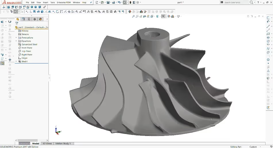
We received the impeller via standard shipment. Our firm is organized into multiple teams. Each team is proficient in its respective domain. First, our 3D scanning team performed a laser scan of the impeller, generating 3D point cloud data. Then our CAD conversion team converted the 3D scan data into a SolidWorks model. However, the model generated had some errors that were due to limitations of the laser scanning technique. In effect, laser scanning works on the principle of reflected rays of light and the features need to be in the line of sight of the scanner in order tp receive and reflect rays of light effectively. This particular impeller possessed an intricate geometry, which in turn limited the laser scanning to function properly. The laser scanned model is shown in figure 1
ERRORS ASSOCIATED WITH LASER SCAN
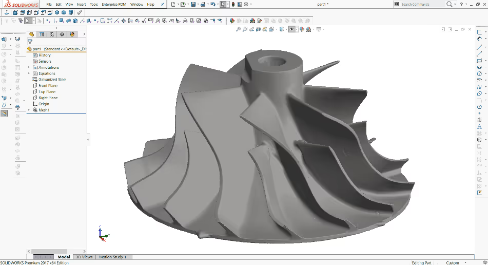
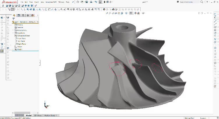
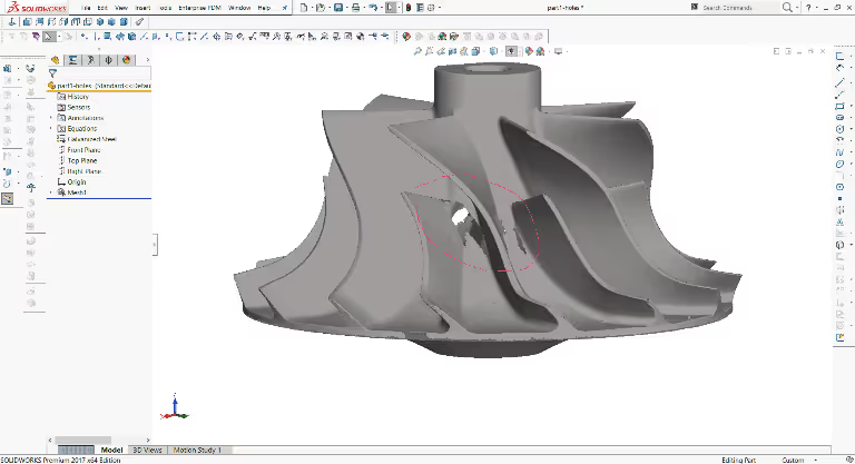
There were numerous errors associated with the laser scanned model such as non-uniform profile, convexity on the surfaces and existence of holes in the scan as shown in figure 2 and figure 3 respectively. The process to fix or repair this 3D scanned model was very cumbersome and, in some cases, it required approximation of the lost details. So, we decided to perform a new scan based on another 3D scanning technique, known as, Computed Tomography scan or CT scan.
WHY CT SCANNING?
The CT scanning method was selected because of the following advantages it possesses over the laser scanning method.
- CT scanning, scans internal geometry of a model effectively, because it scans the object using the amount of radiation that is absorbed by the various parts of the object. Whereas, laser scanning, scans using reflected rays of light. So, a model should be visually cut in order to allow us to verify, all of the internal features by sight.
- Scans based on laser technology distort the physical geometry of a model, due to interference on the complicated regions and hidden regions. This makes it quite difficult to perceive the real object.
- There was no real difference in using white or blue light to differentiate the scanning results.
CT SCAN
Considering the above-mentioned advantages, our 3D scanning team re-scanned the impeller with a CT scanner. The 3D point cloud data was converted into a SolidWorks mesh-based model. The CT scanned model preserved the intricate profiles, and no bulging surfaces and holes were observed. As a result we were able to find out the whole topography of the model, including the internal areas (see fig. 5) with a high precision accuracy equal to 0.0005″. This model was accurate enough to allow for re-manufacturing the same part by generating its CNC codes, for CNC milling.
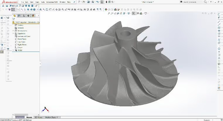
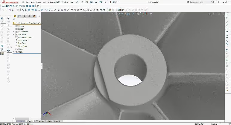
PARAMETRIC MODEL
For future modifications, design assessment and simulation, the client required a parametric model which would be easy for them to modify. Our CAD conversion team was assigned the task of generating a parametric model. The parametric model was generated which incorporated numerous relations and dependencies among the features. It allowed the user to modify any of its parameters and check the result by undergoing simulations of the model. This project was done in Solidworks.
CONCLUSION
In conclusion, CAD / CAM Services provides professional services in Reverse Engineering, 3D Scanning, 3D Modelling, and CAD / CAM projects. We have a team of experienced professionals that provide design and modelling services in SolidWorks, CATIA, UG NX. We have experience in the design and modeling of Aerospace, Navy Vessels, Automobiles (including electric), Pressure Vessels, Tanks and a large variety of other products.
For any projects regarding 3D Modelling, 3D Scanning, CAD Design, Reverse Engineering and CAD / CAM projects, please contact CAD / CAM Services, or get a quote by visiting CAD/CAM Services
